
Car battery charger circuit
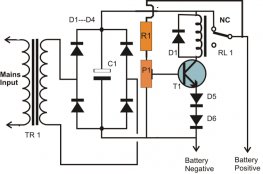
The circuit has been designed to construct a practical mechanism that can easily and automatically charge batteries rated at 6 V or 12 V used in automobiles.
- BC557 – PNP general purpose transistors used for amplification and switching due to its low current and low voltage
- BC547 – NPN small signal transistors designed for general purpose switching and amplification due to its low voltage, low current and three different gain selections
- BD139 – NPN power transistor used for driver stages in hi-fi amplifiers and television circuits because of its low voltage at 80 V maximum and high current at 1.5 A maximum
- 2N3055 – a complementary Silicon Epitaxial-Base planar NPN transistor mounted in Jedec TO-3 metal case for use as power transistor
One of the essential factors in the operation of this circuit is the utilization of transformer denoted as T1 which has excellent resistance and insulation for short circuits making it a good quality. It is responsible for transferring electric energy or alternating current from one circuit to another via conductors that are coupled inductively. A transformer is composed of two or more coils of conducting element, like a wire, wrapped around a core where a magnetic field is produced by an alternating current in one coli. This will induce the same current in the other coils.
The transistor Q1 is conducting through voltage divider R1 and R2 while trimmer TR1 and resistor R4 are functioning as regulated current source. The Darlington pair of power transistors Q5 and Q6 is being driven by a current through R9. A Darlington pair is designed in such a way that the collectors of both transistors are attached together and the emitter of the first transistor is directly coupled to the base of the second or output transistor. The base current of the output transistor is equal to the emitter current of the input transistor. A car battery charger is normally around 6 V to 8 V while the current is around 1.2 A being handled by the trimmer TR1. As the battery is charged slowly, the voltage is gradually increasing until it reaches 7 V, which would cause D1 to conduct. The increase in voltage results to the decrease of voltage across R3 which makes Q1 to conduct. The process will continue until the circuit reaches 6 A. the transistor Q4 will be driven by the voltage drop via R10. Since the transistor Q5 is grounded, the excess current across it would remain constant for modification.
|
Universal Battery Charger, EASTSHINE S2 LCD Display Speedy Smart Charger for Rechargeable Batteries Ni-MH Ni-Cd AA AAA Li-ion LiFePO4 IMR 10440 14500 16340 18650 RCR123 26650 Speakers (EASTSHINE)
|
|
Beatit 600A Peak 14000mAh 12-Volt Portable Car Jump starter Booster Battery Charger Power Pack Vehicle Emergency Kit, Compass & Built-in LED Flashlight Automotive Parts and Accessories (BEATIT TECH)
|
|
|
Arteck Car Jump Starter Auto Battery Charger and 8000mAh External Battery Charger Car Jumper for 12V Automotive, Motorcycle, Tractor, Boat, Phone with Clamps, LED Flashlight, 300A Peak 2.5L Gas Max Automotive Parts and Accessories (Arteck)
|
Related posts:
 Coffee Cup Power Inverter ($34.99) ThinkGeek This doohickey looks like a cup of coffee and fits in your - you guessed it - cup holder. Do not fill it with coffee…
 Being pulled over by a police officer for speeding is the beginning of a series of unfortunate events that costs people money and time, at the very least. Smart…
 The circuit has been designed to construct a practical mechanism that can easily and automatically charge batteries rated at 6 V or 12 V used in automobiles. BC557…
 Q7 HUD GPS Head Up Display! Q7 HUD is specially designed for preventing accident, which can project important information ( e.g. vehicle speed ) onto the front windshield…
 This USB car charger is a great little unit. It comes in a small white box with the unit and the Quick User guide. The 4 ports mean that one can plug in their phone…